


1401, Block B, Jinyu International Center, Changping District, Beijing
Views: 0 Author: Site Editor Publish Time: 2026-09-02 Origin: Site


Reliable DC power forms the foundation of modern telecommunications infrastructure. When critical base stations or data centers go dark, network outages usually tie back to power conversion failures. These interruptions cost companies millions in lost revenue. Customer trust degrades rapidly during unexpected downtime. Upgrading or specifying new power infrastructure demands more than basic AC-to-DC conversion knowledge. You must understand how high-efficiency modules directly impact thermal management. We need to evaluate their effect on operational expenses. System redundancy relies heavily on these specific hardware choices. This comprehensive guide breaks down the core working principles of a Telecom Rectifier Module. You will discover a robust technical evaluation framework. We provide practical insights to support reliable procurement. Your engineering team can use this data to build resilient, future-proof infrastructure planning.
A telecom rectifier module primarily converts alternating current (AC) grid power into stable 48V direct current (DC) using high-frequency switching and active power factor correction (APFC).
Modern procurement focuses on modules offering 96%+ efficiency, minimizing heat dissipation and reducing operational cooling costs.
Enterprise-grade modules require N+1 redundancy, hot-swappable architectures, and strict compliance with telecommunications standards (e.g., NEBS, CE, UL).
Evaluating a rectifier requires balancing form factor (power density) with thermal limitations and integration capability with existing power shelves.
The conversion process begins at the input stage. The module takes in raw alternating current from the local grid. Telecom sites encounter wildly fluctuating power quality. Consequently, a robust Telecom Rectifier Module typically supports a wide voltage range, often spanning from 85V to 290V. The input stage utilizes heavy-duty filtering mechanisms. EMI (Electromagnetic Interference) filters block external grid noise. They prevent high-frequency noise from entering the sensitive module circuitry. Furthermore, these filters stop internal switching noise from leaking back onto the public power grid.
Once filtered, the AC passes into the Active Power Factor Correction circuit. Normal AC-DC conversion heavily distorts electrical waveforms. APFC actively aligns the input current waveform to match the voltage waveform. This alignment achieves a high power factor, usually ≥0.99. A high power factor eliminates reactive power waste. Utility companies often penalize sites showing poor power factors. During grid outages, high power factors maximize backup generator efficiency. Generators run cooler and more consistently when they supply cleanly aligned power.
The APFC stage produces a high-voltage direct current. This voltage remains too high for telecom equipment. The DC-DC conversion stage solves this problem. It steps the high voltage down to the telecom standard, which is usually -48V DC. Modern modules achieve this using high-frequency switching. Engineers employ advanced semiconductors like MOSFETs or IGBTs. These switches turn the DC voltage on and off thousands of times per second. High-frequency switching drastically reduces the physical size of required internal transformers. It drives higher power density and better overall efficiency.
The step-down process creates voltage ripples. Sensitive telecom radios cannot operate reliably on fluctuating power. The final output stage employs specialized LC (inductor-capacitor) filters. These filters smooth the rippling voltage into a perfectly flat -48V DC line. Microprocessors monitor the output voltage continuously. If load demands spike, the processor instantly adjusts the switching cycle. This regulation ensures clean, uninterrupted power delivery. Clean power guarantees stable signal transmission for both baseband units and remote radio heads.
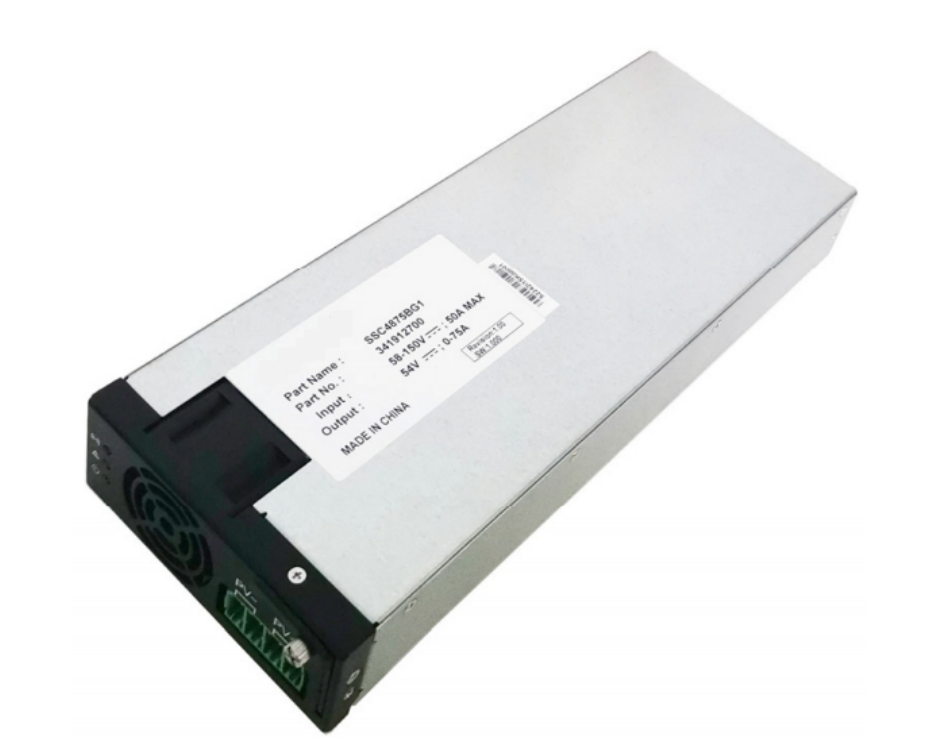
Legacy power systems relied on bulky low-frequency transformers. They were heavy, inefficient, and generated massive heat. Modern architectures shift toward high-frequency, solid-state topologies. Silicon Carbide (SiC) and Gallium Nitride (GaN) components now dominate premium modules. These wide-bandgap semiconductors handle higher operating temperatures. They switch faster than traditional silicon. This speed allows engineers to shrink passive components. The result is a much lighter, significantly more efficient module.
Thermal management dictates module longevity. Heat degrades electronic components quickly. Manufacturers primarily use two cooling strategies: natural convection and forced-air cooling. Forced-air cooling utilizes high-speed DC fans. Fans allow extremely high power densities in small form factors. However, fans introduce a mechanical failure point. Dust and debris can jam fan bearings. Natural convection relies on large heat sinks. It eliminates moving parts entirely. This increases the Mean Time Between Failures (MTBF). The trade-off is a significantly larger physical footprint.
Feature | Forced-Air Cooling (Fans) | Natural Convection (Fanless) |
|---|---|---|
Power Density | Extremely High (Compact size) | Lower (Requires larger footprint) |
MTBF (Reliability) | Moderate (Fans can fail) | Very High (No moving parts) |
Maintenance Needs | High (Filter/Fan cleaning required) | Low (Virtually maintenance-free) |
Ideal Deployment | Space-constrained indoor cabinets | Harsh outdoor or dusty environments |
Modern modules are highly intelligent. They contain dedicated microprocessors, usually DSPs (Digital Signal Processors) or MCUs (Microcontroller Units). These chips perform real-time voltage regulation. They monitor internal temperatures continuously. The microprocessors handle autonomous load sharing between parallel units. They communicate with the central supervisory controller. Communication happens via standard protocols like CAN bus or RS485. If a module detects an internal fault, it alerts the controller immediately. The system can then reroute power dynamically.
You must frame efficiency as a direct operational outcome. A seemingly small efficiency gain yields massive financial savings. Consider a 92% efficient module versus a 98% efficient module. The 92% unit wastes 8% of incoming power as heat. The site HVAC system must work harder to remove this heat. Across a 5-year lifecycle spanning 100+ cell sites, the energy costs multiply rapidly. Upgrading to a 98% efficient module drastically cuts utility bills. It reduces the mechanical wear on site cooling systems.
Space presents a major constraint in modern deployments. 5G edge computing sites often squeeze into tiny urban cabinets. You must evaluate the module's power density. Engineers measure this in watts per cubic inch (W/in⊃3;). High power density frees up rack space for revenue-generating IT equipment. However, extreme density concentrates heat. You must verify thermal stability. The power shelf must provide adequate airflow. Packing modules too tightly causes thermal throttling.
Grid stability varies wildly by geographic location. Rural and remote deployments face frequent voltage sags. Sudden surges occur during industrial equipment startups nearby. Your chosen modules must handle extreme voltage fluctuations. If a module drops the load during a minor sag, the site relies on battery reserves prematurely. Premature battery cycling degrades battery lifespan. Wide input tolerance allows the module to sustain output power without switching to batteries. This capability protects your expensive battery plant.
Telecom loads grow over time. You need systems capable of seamless expansion. Assess the module's parallel operation capabilities. Multiple modules must stack together inside a power shelf. They must actively share the total electrical load. Look for autonomous current sharing features. High-quality modules maintain current sharing accuracy of ≤±5%. If one module supplies 10 amps, the parallel module should supply approximately 10 amps. Perfect balancing prevents individual units from overheating. It maximizes the lifespan of the entire power array.
Telecommunications networks operate continuously. Maintenance windows cannot disrupt active traffic. True zero-downtime maintenance requires hot-swappable architectures. Technicians must slide modules in and out of live power shelves safely. This requires blind-mating connectors on the backplane. The module must feature inrush current limiting circuitry. Without this protection, plugging in a new module creates a massive voltage spike. Voltage spikes can fry downstream routers and radios. Improper seating also causes arcing. Train technicians to engage mechanical locking latches fully.
Enterprise reliability demands strict redundancy models. You must size your power systems using the N+1 methodology. "N" represents the exact number of modules required to support the site load. The "+1" represents a single backup module. Consider a site drawing 12kW of continuous power. You select modules rated at 3kW each. You need four modules to meet the 12kW demand (4 x 3kW = 12kW). To achieve N+1, you install five modules. The system now has 15kW of capacity. If one unit fails, the remaining four seamlessly cover the 12kW load. This guarantees continuous operation.
Catastrophic grid events happen. Lightning strikes utility lines. Transformers explode. Your module acts as the final barrier between grid chaos and expensive telecom assets. Robust Over-Voltage Protection (OVP) is mandatory. If the output voltage exceeds safe thresholds, the module must shut down instantly. Over-Current Protection (OCP) defends against short circuits. If a downstream cable shorts, the module limits the current output. It isolates itself to prevent internal fires. Once the fault clears, intelligent modules attempt automatic recovery.
Carrier-grade environments demand rigorous compliance. You cannot deploy uncertified equipment safely. Shortlisting criteria must mandate specific regulatory verifications. NEBS Level 3 remains the gold standard for North American telecommunications. It tests for seismic resilience, fire resistance, and extreme temperature tolerance. Modules must meet UL/EN 62368-1 safety standards for information technology equipment. RoHS compliance ensures the manufacturer avoids hazardous heavy metals. Meeting these standards reduces liability. It simplifies the site inspection and insurance processes.
Evaluate Legacy Compatibility: You must determine if a full forklift upgrade is necessary. Sometimes, new modules integrate smoothly into existing backplanes. They might communicate flawlessly with legacy monitoring controllers. If the manufacturer uses proprietary communication protocols, integration becomes difficult. Open protocols like SNMP or standard CAN bus simplify retrofits. Replacing an entire power shelf requires extensive downtime. Pin-compatible module upgrades save time and capital.
Analyze Lifecycle Performance Value: You must move beyond the initial unit purchase price. Analyze the long-term operational impact. Factor in the localized cooling requirements. High efficiency reduces the need for expensive HVAC upgrades. Examine the stated MTBF carefully. Enterprise models should exceed 300,000 hours of continuous operation. Review the warranty terms. Extended warranties indicate manufacturer confidence. Long-lasting modules reduce truck rolls and maintenance labor overhead.
Assess Vendor Support and Supply Chain: Hardware is only part of the equation. Assess the manufacturer's operational capabilities. Can they provide regular firmware updates? Modern rectifiers need security patches just like IT servers. You need localized technical support for complex troubleshooting. Large-scale rollouts require stable supply chains. Verify standard lead times for bulk orders. Vendor instability creates costly deployment delays.
The basic working principle of a telecom rectifier module appears straightforward at first glance. It efficiently converts raw alternating current into stable direct current. However, the exact engineering execution dictates ultimate network reliability. High-frequency conversion, active power factor correction, and intelligent thermal management separate basic supplies from carrier-grade solutions.
We recommend basing your final procurement decisions on verifiable data. Request efficiency curves from manufacturers. Scrutinize their proven thermal management designs. Ensure the modules integrate seamlessly with your existing intelligent site controllers. As a next step, consult directly with your field engineering teams. Audit your current site power loads carefully. Define your exact N+1 redundancy requirements based on projected growth. Finally, request evaluation units from your shortlisted manufacturers to run controlled lab tests.
A: The industry standard is -48V DC. Early telephone networks adopted this specific voltage because it strikes a perfect balance. It delivers enough power over long copper lines while remaining below the threshold for lethal electric shock. The negative polarity actively helps prevent galvanic corrosion on underground wires.
A: Telecom modules prioritize extreme network reliability. They feature hot-swap capabilities for zero-downtime maintenance. They include intelligent, autonomous load-sharing protocols to balance power across multiple units. Industrial supplies often lack these telecom-specific communication protocols and blind-mating hardware features.
A: When AC grid power fails, the rectifier module instantly stops converting power. However, the site does not go down. The telecom site's battery backup system connects directly to the same shared DC bus. The batteries seamlessly take over the load without any switching delay.
A: Engineers generally discourage mixing different module capacities. Parallel load sharing relies on identical internal resistance and control logic. Mixing wattages can confuse the current-sharing algorithms. It often forces the smaller modules to run constantly at maximum load, accelerating their physical degradation. Only mix capacities if the specific system controller explicitly supports it.